Find the right clearance, fast
Looking for a dependable journal bearing clearance chart that covers every common shaft diameter with easy-to-use tolerances? This guide distills best practices for hydrodynamic, Babbitt-lined journal bearings into clear ranges you can apply during design, rebuilds, and inspections. You will also find practical tips for measurement, adjustment, and troubleshooting so you can keep equipment running cool, quiet, and reliable. For a downloadable version, contact Fusion Babbitting and ask for our journal bearing clearance chart PDF.
What is journal bearing clearance?
Journal bearing clearance is the intentional gap between a rotating shaft and the bearing surface. In Babbitt-lined bearings, this gap allows an oil film to form as the shaft rotates. That film supports the shaft on a wedge of lubricant, which prevents metal contact, controls temperature, and reduces wear. Clearance is typically measured in two ways. Diametral clearance is the total difference between the bore diameter of the bearing and the diameter of the journal. Radial clearance is half of the diametral clearance. Most charts and rebuild specifications call out diametral clearance. When in doubt, confirm which one your document uses.
Why clearance matters for reliability
The right clearance helps the oil film develop and stay stable across the full range of speeds, loads, temperatures, and alignment conditions. Too little clearance can lead to metal-to-metal contact, high friction, wiped Babbitt, and elevated temperatures. Too much clearance can increase vibration, reduce stiffness, cause oil leakage, and promote instability like subsynchronous whirl. A sound journal bearing clearance chart lets you balance these tradeoffs and set a target that matches your machine and service conditions.
How to read and apply the journal bearing clearance chart
The journal bearing clearance chart below provides typical diametral clearance ranges for general-purpose Babbitt-lined hydrodynamic bearings in industrial service. These ranges are intended for steady operating speeds and mineral oil lubrication under normal loads. Use them during initial sizing, for quick checks during rebuilds, and as a starting point when reverse engineering an obsolete part. Always confirm against OEM specifications, especially for high-speed turbomachinery or unusual operating conditions.
Standard tolerances by shaft diameter
Under 1.00 inch diameter
- Recommended diametral clearance: 0.0008 to 0.0012 inch
- Radial clearance: 0.0004 to 0.0006 inch
- Metric reference: 20 to 30 micrometers diametral
- Notes: Small shafts are sensitive to bore geometry and finish. Aim for a fine finish and tight roundness control.
1.00 to 2.00 inches diameter
- Recommended diametral clearance: 0.0010 to 0.0025 inch
- Radial clearance: 0.0005 to 0.0013 inch
- Metric reference: 25 to 65 micrometers diametral
- Notes: Good for many electric motors, pumps, and small turbines when using ISO VG 32 to 68 oils.
2.01 to 4.00 inches diameter
- Recommended diametral clearance: 0.0020 to 0.0040 inch
- Radial clearance: 0.0010 to 0.0020 inch
- Metric reference: 50 to 100 micrometers diametral
- Notes: A common range for mid-size motors and process pumps. Verify endplay and alignment to avoid edge loading.
4.01 to 6.00 inches diameter
- Recommended diametral clearance: 0.0030 to 0.0060 inch
- Radial clearance: 0.0015 to 0.0030 inch
- Metric reference: 75 to 150 micrometers diametral
- Notes: Larger diameters see more thermal growth. Confirm operating temperature, oil viscosity, and housing rigidity.
6.01 to 8.00 inches diameter
- Recommended diametral clearance: 0.0045 to 0.0080 inch
- Radial clearance: 0.0023 to 0.0040 inch
- Metric reference: 115 to 200 micrometers diametral
- Notes: Good for heavy pumps, gearboxes, and small turbines. Consider a groove configuration that maintains oil film stability.
8.01 to 12.00 inches diameter
- Recommended diametral clearance: 0.0060 to 0.0120 inch
- Radial clearance: 0.0030 to 0.0060 inch
- Metric reference: 150 to 300 micrometers diametral
- Notes: Used in mills, marine shafts, and hydro equipment. Oil delivery and drainback design become critical.
Over 12.00 inches diameter
- Recommended diametral clearance: 0.0100 to 0.0200 inch
- Radial clearance: 0.0050 to 0.0100 inch
- Metric reference: 250 to 500 micrometers diametral
- Notes: For large, slow-speed journals, emphasize alignment and load distribution. Confirm shell rigidity and support structure.
Rule-of-thumb check
As a quick sense check, many applications fall near a diametral clearance ratio of 0.001 to 0.002 times the shaft diameter in inches. For example, a 4 inch shaft might use 0.004 to 0.008 inch diametral clearance. This is not a substitute for OEM specifications, but it helps flag outliers during inspections or reverse engineering.
When to adjust the chart for your conditions
The journal bearing clearance chart above is a strong starting point. Certain conditions may justify small adjustments. Keep changes conservative and verify with thermal and performance checks.
- High speed: May require a slightly larger clearance to maintain a stable oil wedge and limit heat rise.
- Heavy unit load: Often benefits from modestly larger clearance for film strength, though stiffness can drop if you increase too much.
- Low speed or oscillating motion: May run better with slightly tighter clearances to reduce mixed lubrication time.
- High operating temperature: Allow for thermal growth of both shaft and housing. Slightly more clearance at ambient can be helpful.
- Low viscosity oil: May need a small increase to promote film thickness. For higher viscosity oils, the chart range is generally sufficient.
- Soft Babbitt grades: Can tolerate slight deviations, but aim for the midpoint of the chart to reduce risk of wipe or fatigue.
- Precision rotors: For tight vibration limits, stay toward the lower end of the range and control roundness and alignment carefully.
Surface finish, roundness, and geometry tolerances
Clearance is only one piece of the bearing performance puzzle. To get consistent film formation, maintain the following features:
- Surface finish: 16 microinch Ra or better on the journal is a common target. Match the finish to the oil cleanliness and speed.
- Roundness and taper: Keep roundness and taper within a small fraction of the total clearance. As a guide, limit bore out-of-round to less than 25 percent of radial clearance.
- Alignment: Poor alignment causes edge loading and wipes, even when nominal clearance is correct.
- Bearing geometry: Features such as grooves, reliefs, and pockets should be smooth and located to support a stable hydrodynamic wedge.
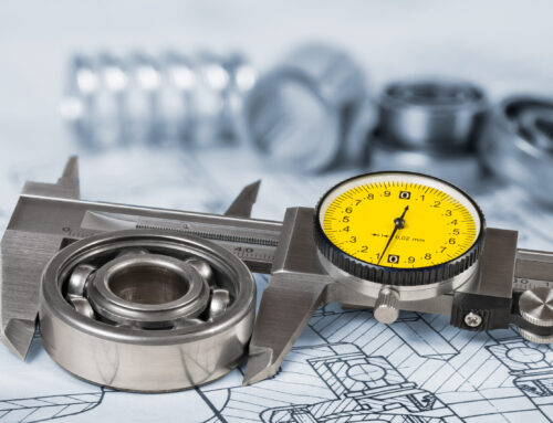
How to measure and verify bearing clearance
Verification during rebuilds or inspections ensures that the final clearance matches intent. Here are common methods used by Fusion Babbitting and field technicians.
- Measure the shaft: Use a calibrated micrometer to measure the journal at several axial and circumferential points. Note average diameter and any taper or ovality.
- Measure the bore: Use an inside micrometer or bore gauge to check bearing ID at multiple locations. For split shells, measure each half and verify crush and fit.
- Calculate the diametral clearance: Subtract the average journal diameter from the measured bore diameter. Compare to the journal bearing clearance chart range.
- Use plastigage for a quick check: For assembled bearings, plastigage can give a fast read on clearance. Follow manufacturer instructions and record the measured thickness.
- Confirm contact pattern: Apply a light blueing or transfer medium on the journal. Rotate gently to verify the contact pattern is even and consistent.
- Document and tag: Record measured values on a work traveler or inspection sheet. This creates traceability and supports future overhauls.
Symptoms of incorrect clearance
Spotting the signs early prevents secondary damage to rotors, housings, and couplings. Watch for the following during startup and operation.
- Overheating: Bearing metal temperatures rising quickly at startup or trending upward under steady loads.
- Vibration: Increase in subsynchronous components or broad-band vibration that changes with load or temperature.
- Oil leakage: Excess oil flow at seals and drains can point to an oversized clearance.
- Noise: Rubbing or squeal at low speeds may indicate too little clearance or poor alignment.
- Metal debris: Silver or gray particles in filters or oil samples signal Babbitt distress.
- Wiped areas: Visible smear, scoring, or discoloration on the Babbitt surface during inspection.
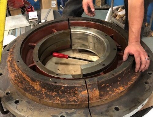
Reverse engineering obsolete bearings
Many plants run legacy equipment where OEM parts are no longer available. Fusion Babbitting reverse engineers these bearings by combining dimensional inspection with material analysis and performance targets. Our team produces drawings, confirms clearances against the journal bearing clearance chart, and validates final geometry so your replacement runs like the original or better. This service is valuable for paper mills, mines, marine repair yards, and utilities that rely on specialized housings and shaft sizes.
How Fusion Babbitting ensures accurate clearances
Fusion Babbitting Co., Inc., established in 1988 and based in Milwaukee, provides a full suite of Babbitt bearing services. With over 40 years of combined expertise, our technicians apply proven processes and advanced equipment to deliver bearings that meet or exceed OEM specifications. Here is how we control and verify clearances.
- Centrifugal casting: We cast certified Babbitt using centrifugal methods for uniform bonding and density. This supports precise machining of bore size and geometry.
- Arc flame spray application: When restoring worn components, we rebuild diameters and machine back to target dimensions for correct fit and clearance.
- Precision machining: We hold tight tolerances on roundness, taper, and surface finish so the measured clearance matches the intended design value.
- Reverse engineering: For obsolete or undocumented bearings, we create detailed drawings and validate the final bore against the journal bearing clearance chart before shipment.
- Quality inspection: Every part is checked with calibrated instruments. We document bore sizes, crush, and clearances so your installation is predictable.
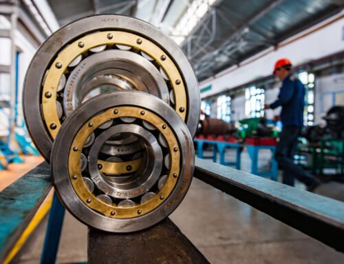
Industries and applications served
Fusion Babbitting supports demanding environments where reliable bearings protect high-value assets. We serve aluminum mills, cement and chemical plants, fossil and nuclear plants, hydro and pump storage facilities, marine repair, mines and steel mills, motor repair shops, paper mills, shipyards, and crushed stone producers. Common applications include electric motors, pumps, turbines, and hydro power systems. Whether you need repair, rebabbitting, rebuilding, or new manufacturing, we match the bearing clearance to your speed, load, and lubrication plan.
Practical tips for using the chart in maintenance planning
- Record as-found data: During teardown, measure journal diameter and bore ID. Use the journal bearing clearance chart to benchmark your findings.
- Check at operating temperature: Consider thermal growth. A bearing that is tight at ambient may be correct at temperature or vice versa.
- Standardize by equipment class: Group machines by shaft size and duty. Assign a standard clearance target for each group to streamline rebuilds.
- Align with oil selection: Match clearance to viscosity. If you standardize on an ISO VG 68 oil, pick a midpoint in the range that supports film thickness.
- Verify seals and drains: Excessive clearance can overwhelm seals and drain paths. Ensure the housing design supports your chosen tolerance.
- Plan for contingencies: Keep a record of acceptable alternate clearances for emergency repairs so you can return to service quickly.
Frequently asked questions
Is the chart diametral or radial clearance?
All values in this article are diametral unless noted. Radial clearance is half of the diametral clearance.
Can I use the same clearances for bronze or polymer-lined bearings?
The ranges here focus on Babbitt-lined hydrodynamic bearings. Bronze or polymer materials can behave differently. Confirm with material guidance or contact Fusion Babbitting for recommendations.
How tight is too tight?
If your measured diametral clearance is below the low end of the range, you risk metal contact during start, stop, or transients. This is a common cause of wipe. Increase clearance or adjust alignment and oil viscosity.
How loose is too loose?
If the clearance is well above the high end, you may see elevated vibration, instability, and leakage. In many cases, reducing clearance to the midpoint of the range restores stability.
Do split bearings need special consideration?
Yes. Verify crush, fit, and cap alignment. Measure each half to ensure the assembled bore is round and within tolerance. A correct assembled clearance prevents edge loading and hot spots.
Why plants choose Fusion Babbitting for bearing projects
Fusion Babbitting brings together fast response, skilled craftspeople, and modern tooling. We offer repair, rebabbitting, and rebuilding that meet or exceed OEM specifications. Our centrifugal casting process ensures strong bond strength. Our arc flame spray application restores worn components back to original size. We can handle parts up to 120 inches in diameter and length, and we provide 24-hour emergency service. When you need a new bearing manufactured for an OEM application, or a reverse-engineered replacement for a legacy asset, our team will deliver a precise fit backed by clear documentation. We do this work every day for customers nationwide from our Milwaukee facility at 4540 W. Burnham St.
Get your downloadable journal bearing clearance chart
If you want a quick reference you can print and post in your shop, ask for our free journal bearing clearance chart PDF. It lists standard tolerances by shaft diameter, plus quick rules of thumb and measurement notes. Contact Fusion Babbitting at 414.645.5800 or 800.613.5118, or email sales@fusionbabbitting.com. We will help you choose the right clearance for your application, confirm material selection, and schedule repair or new manufacturing as needed.
Final takeaway
A clear, well-structured journal bearing clearance chart is one of the most useful tools in your reliability playbook. It helps you size new parts, verify rebuilt components, and diagnose performance issues before they become failures. Use the ranges in this guide as a dependable starting point, then fine tune for speed, load, temperature, and oil viscosity. If you need expert support, Fusion Babbitting is ready to help with repair, rebabbitting, rebuilding, reverse engineering, and custom manufacturing for bearings across industries. Call or email today to improve bearing performance and machine uptime with confidence.
About Fusion Babbitting
Fusion Babbitting Co., Inc. specializes in Babbitt bearing services and has been serving customers since 1988. Located at 4540 W. Burnham St., Milwaukee, WI 53219, we provide nationwide coverage and 24-hour emergency response. Services include repair, rebabbitting, rebuilding, centrifugal casting, arc flame spray application, reverse engineering with detailed drawings, general fabrication and machining up to 120 inches, and new manufacturing for OEMs. We support aluminum mills, cement and chemical plants, fossil and nuclear plants, hydro and pump storage, marine repair, mines and steel mills, motor repair shops, paper mills, shipyards, and crushed stone producers. Applications include electric motors, hydro power systems, pumps, and turbines. Contact us at 414.645.5800 or 800.613.5118, or email sales@fusionbabbitting.com to discuss your project and request the journal bearing clearance chart.