Sleeve bearing clearance made simple. When you size the oil film gap correctly, your equipment starts easier, runs cooler, resists wear, and lasts longer. The 0.001 rule gives you a fast, reliable way to set base clearance, then adjust for speed, load, oil, and temperature. In this guide, you will learn how to calculate sleeve bearing clearance step by step, how to validate it, and how to avoid the most common mistakes. If you need expert help, Fusion Babbitting is ready to support you with repair, rebabbitting, reverse engineering, and new manufacturing for critical bearings across the United States.
What Is Sleeve Bearing Clearance
Sleeve bearing clearance is the small, controlled gap between a rotating journal and the surrounding bearing surface. Oil fills this gap and forms a pressurized film that separates metal surfaces during operation. This oil film is what prevents wear, keeps temperatures in check, and cushions dynamic loads. Too little clearance and you risk metal contact, scoring, and rapid failure. Too much clearance and the oil film loses stiffness, which invites vibration, oil whirl, heat, and leakage. Finding the sweet spot is essential for reliability.
Why Clearance Matters
The right clearance lets the bearing work in full hydrodynamic lubrication. As the shaft spins, it drags oil into the wedge-shaped gap and builds pressure that supports the load. Proper clearance improves:
- Oil film stability and stiffness
- Temperature control and heat removal
- Start-up protection under mixed or boundary lubrication
- Vibration control and noise reduction
- Service life of both journal and bearing lining
In contrast, incorrect sleeve bearing clearance can lead to wipe, discoloration, babbitt fatigue, and unplanned downtime. A small mistake on clearance can compound with oil selection, alignment, and operating conditions.
The 0.001 Rule Explained
The 0.001 rule is a proven rule of thumb for sizing base clearance. In simple terms, start with a radial clearance equal to 0.001 inch per inch of journal diameter. That means diametral clearance is about 0.002 inch per inch of diameter. In metric, radial clearance is roughly 0.001 mm per mm of journal diameter, with diametral clearance about 0.002 mm per mm. Use this as a starting point, then tune it based on speed, viscosity, load, geometry, and temperature.
Quick examples
Example in inches: A 4.000 inch journal. Base radial clearance equals 0.001 x 4.000, which is 0.004 inch. Base diametral clearance is twice that at 0.008 inch. Example in metric: A 100 mm journal. Base radial clearance equals 0.001 x 100, which is 0.100 mm. Base diametral clearance is 0.200 mm. These values set the baseline. You will refine them for your application using the steps below.
How to Calculate Sleeve Bearing Clearance With the 0.001 Rule
- Define the journal size and service. Record the journal diameter, speed range, load, duty cycle, operating temperature, and lubrication method, such as ring oil, forced oil, or bath.
- Choose a base clearance with the 0.001 rule. Start with radial clearance at 0.001 x journal diameter. Note the matching diametral clearance at two times the radial value.
- Confirm oil viscosity. Select the oil grade recommended by the equipment maker or determine an ISO VG based on speed and temperature. Heavier oils often need a touch more clearance for start-up, while very light oils can support tighter clearance.
- Adjust for speed. Higher speed tends to support thinner films, but also raises heat. For high speed service, add a small increment to the base clearance to prevent thermal rubs. For low speed or oscillating motion, you may only need the base value or a small reduction.
- Account for load. Heavy radial loads and shock loads call for a robust film. Increase clearance slightly only if temperatures or start-up friction are concerns. Do not reduce clearance below the base without expert analysis, since boundary lubrication may occur at start-up.
- Consider temperature and growth. Hot shafts expand. Bearing housings change size with heat. Estimate shaft and housing growth so your hot running clearance remains safe. This usually means adding a small amount to cold clearance on machines that run hot.
- Review geometry and surface finish. Roundness, taper, alignment, and surface finish influence film formation. Journals should be smooth and round, typically 8 to 16 microinch Ra. Babbitt surfaces often finish in the 32 to 63 microinch Ra range. If geometry is not ideal, do not tighten clearance to compensate. Fix the geometry or adjust clearance to protect the film.
- Validate with operating history. Look at prior temperatures, oil analysis, and vibration. If the bearing ran hot or showed wear, increase clearance slightly or choose a higher viscosity. If it leaked oil or vibrated, consider tightening slightly or improving alignment.
- Document the final target. Record the final cold build radial and diametral clearance, measurement method, and tolerance. Include any split bearing parting line targets.
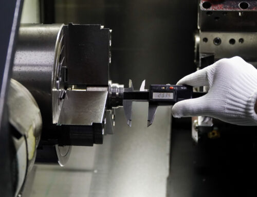
- Measure and verify during assembly. Use micrometers, a bore gauge, and calibrated standards. Confirm clearance in at least two planes 90 degrees apart. If needed, validate with Plastigage at assembly as a cross-check.
Typical Adjustments and Practical Ranges
The base 0.001 rule works across many motors, pumps, and turbines. The adjustments below are practical guides. Always consider OEM guidance and the advice of specialists like Fusion Babbitting.
- High speed service: Consider adding 5 to 15 percent to the base radial clearance to allow for thermal expansion and oil shear heating.
- Heavy oil viscosity: Add up to 10 percent to improve start-up flow, especially in cold environments.
- Light oil viscosity: Reduce up to 10 percent, as long as start-up friction and load capacity remain safe.
- Heavy radial load: Keep to the base value or add up to 10 percent if heat is a concern. Do not go tighter unless supported by detailed analysis.
- High ambient or process heat: Add a small increment so the running hot clearance stays within the target range.
For many electric motors and pumps, the final diametral clearance often lands near 0.001 to 0.002 inch per inch of diameter. Critical turbines and high speed machines may need more careful analysis and grooving patterns to control the film. When in doubt, consult Fusion Babbitting for an engineering review and reverse engineered drawings.
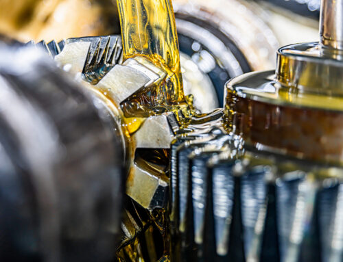
How Oil, Grooves, and Geometry Affect Clearance
Oil viscosity and distribution matter as much as the raw gap size. The goal is a stable wedge of oil that renews itself and carries away heat.
- Oil selection: For moderate temperatures, common choices include ISO VG 32, 46, and 68. Higher speeds often use lighter oils. Higher loads or hot service may need heavier oils.
- Grooving: Axial grooves help delivery and cooling. Circumferential grooves can reduce load capacity. Groove placement and depth affect film stability. Match groove design to your service.
- Surface finish and roundness: Good finish reduces start-up wear. Check for lobing, taper, or out-of-round that can break the oil film at the load zone.
- Bearing length-to-diameter ratio: Shorter bearings have less area to carry load. They may benefit from careful clearance and oil delivery design.
Common Symptoms of Incorrect Sleeve Bearing Clearance
- Overheating soon after start-up or under steady load
- Audible rub, squeal, or chatter
- Wiped or smeared babbitt surface
- High oil consumption and external leakage
- Excessive vibration or oil whirl in the speed range of interest
- Discoloration or softening of bearing metal
- Metal debris in filters or elevated tin, lead, or copper in oil analysis
If you see these signs, plan an inspection. Fusion Babbitting can assess the bearing, measure the clearance, repair or rebabbit the surface, and recommend a revised clearance, oil grade, and groove pattern.
How to Measure and Verify Clearance
Accurate measurement is the backbone of reliable clearance control. Here is a straightforward approach used in professional shops and during field rebuilds.
- Mic the journal: Measure diameter at multiple axial locations and two or more planes. Record average size and any taper or out-of-round.
- Measure the bearing ID: Use a calibrated bore gauge and set master rings. Take readings at several depths and angles to capture true roundness.
- Calculate cold diametral clearance: Bearing ID minus journal OD. Divide by two to get radial clearance.
- Check parting lines: Split bearings may have a slight pinch or relief at the split. Confirm the design intent and measurement technique matches the OEM or shop standard.
- Use Plastigage if needed: As a cross-check on final assembly, Plastigage provides a quick read on assembled clearance.
- Account for thermal growth: Estimate shaft and housing growth from coefficient and temperature change to predict hot running clearance.
Case Example: Applying the 0.001 Rule
A paper mill pump uses a 3.500 inch journal. It runs at 1,780 rpm with ISO VG 46 oil and moderate load. The room is warm, and the pump runs continuously. Base radial clearance with the 0.001 rule is 0.0035 inch. Because speed is moderate and oil is not too heavy, the team keeps the base value. They confirm good journal finish and alignment, validate oil delivery grooves, and assemble with a cold diametral clearance near 0.007 inch. The bearing runs cool with stable vibration. A similar pump in a colder room with thicker oil at start-up might add 10 percent to the base clearance to improve cold flow and reduce start-up friction.
Best Practices to Keep Sleeve Bearing Clearance in the Safe Zone
- Start with the 0.001 rule and adjust based on your specific duty.
- Match oil viscosity to speed and temperature. Check manufacturer guidance.
- Control geometry. Fix taper or out-of-round before chasing clearance.
- Inspect grooves and supply paths. Good oil in and good oil out keep the film stable.
- Measure cold and predict hot. Consider both shaft and housing growth.
- Record everything. Build a history that guides future rebuilds.
- When in doubt, get an expert review. The cost is small compared to a failure.
About Fusion Babbitting
Fusion Babbitting Co., Inc., established in 1988 and based in Milwaukee, WI, is a nationwide leader in Babbitt bearing services. From repair and rebabbitting to rebuilding, reverse engineering, and custom manufacturing, Fusion Babbitting delivers dependable results for critical machines. Located at 4540 W. Burnham St., the team provides 24-hour emergency service when downtime is not an option.
Services that support correct sleeve bearing clearance
- Repair, Rebabbitting, and Rebuilding: Work that meets or exceeds OEM specifications, with attention to clearance, geometry, and finish.
- Centrifugal Casting: Strong bond strength and high integrity using certified Babbitt materials for long, stable service.
- Arc Flame Spray Application: Restores worn components and brings them back to original dimensions so final clearance targets are met.
- Reverse Engineering: Precise replicas of obsolete bearings produced with detailed drawings and verified fits.
- General Fabrication and Machining: Capacity for components up to 120 inches in diameter and length.
- New Manufacturing: Custom, high precision bearing products for OEMs and end users.
Fusion Babbitting supports aluminum mills, cement and chemical plants, fossil and nuclear plants, hydro and pump storage, marine repair, mines and steel mills, motor repair shops, paper mills, shipyards, and crushed stone producers. Typical applications include electric motors, hydro power systems, pumps, and turbines. With more than 40 years of combined expertise, the company uses advanced equipment and skilled specialists to deliver safe, efficient, and reliable machinery performance.
When to Call Fusion Babbitting
Call if you notice hot bearings, wiped metal, unusual vibration, oil whirl, or repeated failures after rebuilds. Also call when you change operating conditions, such as oil grade, process temperature, or speed. The Fusion Babbitting team can review your sleeve bearing clearance targets, inspect the journal and bearing, validate oil groove design, and repair or recast with the right dimensions. Reach the team at 414.645.5800 or 800.613.5118, or email sales@fusionbabbitting.com. The shop is located at 4540 W. Burnham St., Milwaukee, WI 53219.
Frequently Asked Questions
Is the 0.001 rule for radial or diametral clearance
Use the 0.001 rule as a base for radial clearance. That means diametral clearance is about twice the radial value. If you prefer to think in diametral clearance, you can say roughly 0.002 inch per inch of journal diameter. In metric, that is about 0.002 mm per mm for diametral clearance.
Can I tighten clearance to fix vibration
Sometimes a small reduction in sleeve bearing clearance helps, but you should confirm alignment, roundness, balance, and oil supply first. Too tight risks heat and wipe. Make small, planned changes and record the results, or contact Fusion Babbitting for a review.
What affects hot running clearance the most
Shaft and housing thermal growth, oil temperature, and load have strong effects. Different materials expand at different rates. Estimate the hot condition to avoid surprise rubs or leaks.
How do grooves change the needed clearance
Grooves help feed and cool the film but can reduce load capacity if they remove support area in the loaded zone. The right groove pattern often lets you keep a more stable film without over-opening clearance.
What surface finish should I target
Journals often run best around 8 to 16 microinch Ra, while babbitt bearing IDs commonly finish around 32 to 63 microinch Ra. Smooth enough to protect the film, but with surfaces that retain oil during start-up.
A Simple Worksheet You Can Use Today
- Journal diameter: write down D.
- Base radial clearance: 0.001 x D.
- Adjust for speed: add 0 to 15 percent as needed.
- Adjust for viscosity: add 0 to 10 percent for heavier oil at cold start. Reduce up to 10 percent for very light oil if safe.
- Consider temperature: add a small increment if high operating heat is expected.
- Final radial clearance: sum the base and adjustments.
- Final diametral clearance: double the final radial value.
- Document and verify with measurements.
Closing Thoughts
Sizing sleeve bearing clearance does not need to be complex. The 0.001 rule gives you a clear starting point. Build from it with sensible adjustments for speed, oil, load, and temperature. Confirm with careful measurement and solid records. If you do that, your bearings will build a stable, strong oil film that protects your machines and your schedule. When problems appear or when you need a fresh set of eyes, Fusion Babbitting is ready to help with repair, rebabbitting, reverse engineering, and new manufacturing. Contact the team at 414.645.5800 or 800.613.5118, or email sales@fusionbabbitting.com for fast, expert support. Whether you run motors, pumps, turbines, or hydro equipment, getting sleeve bearing clearance right will boost reliability and reduce total cost of ownership.