The Journal Bearing Clearance Chart and Learn How to Measure
Looking for a clear, practical reference on bearing fit? This guide explains the journal bearing clearance chart, how to measure clearance correctly, and what tolerances to consider for different shaft sizes, materials, and speeds. Fusion Babbitting provides a free PDF chart to help technicians, maintenance teams, and engineers set accurate clearances and prevent wear. Request the PDF and learn the right steps to measure and verify your fit, so your machinery runs cooler, quieter, and longer.
What Is Journal Bearing Clearance and Why It Matters
Journal bearing clearance is the difference between the bearing bore diameter and the shaft journal diameter. It is measured as diametral clearance across the full bore or radial clearance as half that value. Correct clearance allows oil to form a stable hydrodynamic film. That film separates metal surfaces, carries load, controls temperature, and reduces friction.
Too little clearance risks metal-to-metal contact, rapid heat rise, and seizure. Too much clearance can reduce film stability, increase vibration, and lower oil film thickness at the loaded zone. Both extremes shorten bearing life. The right range depends on shaft diameter, operating speed, load, lubricant viscosity, and bearing material. The journal bearing clearance chart provides typical ranges so you can compare your measurements with expected values and OEM recommendations.
Journal Bearing Clearance Chart: Quick Reference Ranges
The Fusion Babbitting journal bearing clearance chart offers a practical starting point. Always verify with OEM specifications and the application’s engineering requirements. These ranges are general guidelines for Babbitt-lined journal bearings in good condition using appropriate oil viscosity and standard operating temperatures.
- Shaft diameter 0.75 to 1.5 in: Target diametral clearance 0.0010 to 0.0025 in
- Shaft diameter 1.5 to 3.0 in: Target diametral clearance 0.0015 to 0.0030 in
- Shaft diameter 3.0 to 6.0 in: Target diametral clearance 0.0020 to 0.0040 in
- Shaft diameter 6.0 to 12.0 in: Target diametral clearance 0.0030 to 0.0060 in
- Shaft diameter 12.0 to 24.0 in: Target diametral clearance 0.0040 to 0.0090 in
- Over 24.0 in: Engineered case-by-case based on load, speed, geometry, and oil system
Adjust ranges based on operating conditions:
- High speed and light load: Consider the low end of the range for film stability
- Low speed and heavy load: Consider the high end of the range to allow more oil and thermal growth
- Higher viscosity oil or cooler ambient conditions: Clearance can be slightly tighter
- Lower viscosity oil or hotter ambient conditions: Clearance may need to be slightly larger
Material adjustments are also important:
- Tin-based Babbitt: Good for higher speeds and moderate loads. Standard ranges in the chart generally apply
- Lead-based Babbitt: Often used in lower-speed or heavier-load applications. Slightly larger clearance may be appropriate
- Bronze-backed shells or steel-backed shells: Backing material influences heat transfer and stiffness. Follow OEM or Fusion Babbitting recommendations
How to Measure Journal Bearing Clearance
Tools You Will Need
- Outside micrometer matched to the journal diameter
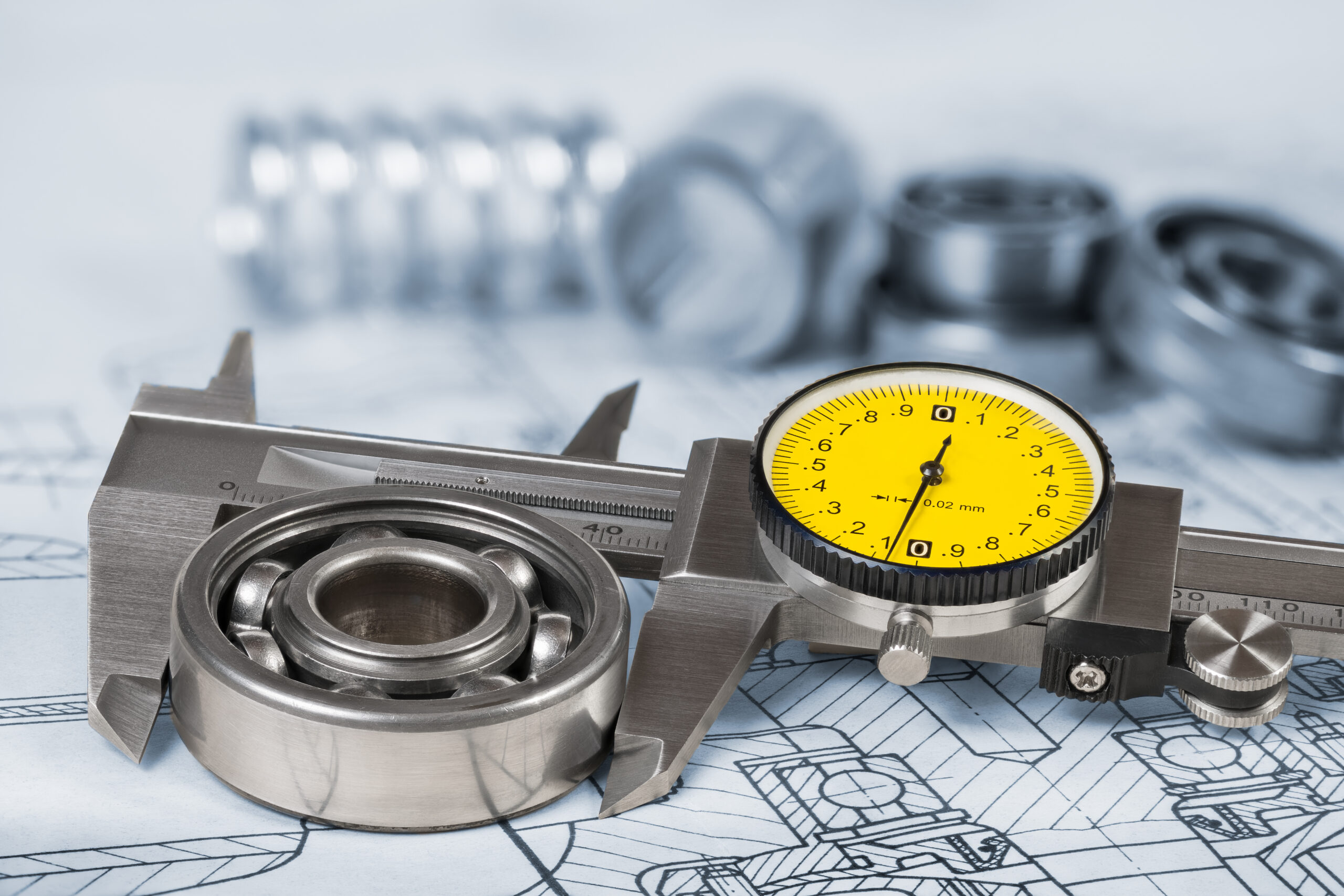
- Dial bore gauge or internal micrometer for the assembled bearing bore
- Calibration standards and gauge blocks to verify accuracy
- Torque wrench for cap bolts
- Feeler gauges and telescoping gauges for cross-checks
- Plastigage for a quick verification where appropriate
- Dial indicator for runout checks
- Surface plate or stable bench and V-blocks
- Prussian blue for contact pattern checks
- Solvent and lint-free wipes for cleaning mating surfaces
- Thermometer or infrared thermometer to record part temperature
Step-by-Step Measurement Procedure
- Clean and prepare. Remove oil, debris, and old shims. Wipe the bearing shells and journal with lint-free wipes. Ensure the work area is clean and stable
- Stabilize temperature. Let the bearing shells and the shaft reach the same ambient temperature. Temperature differences change dimensions and can skew results
- Confirm nominal sizes. Note the shaft nominal diameter and the expected bore size. Review OEM specs if available. If no OEM specs exist, use the journal bearing clearance chart as a starting reference
- Inspect the shells. Look for wipe marks, scoring, cracks, lifted Babbitt, porosity, and fretting. Check parting lines, oil grooves, and any anti-rotation tabs or dowels
- Measure the shaft journal. Use a micrometer to measure the journal at 0 degrees and 90 degrees, and at multiple locations along the length of the bearing surface. Record minimum, maximum, taper, and out-of-round. Typical runout for precision assemblies should be significantly less than total clearance
- Assemble the bearing. Install the lower and upper shells in the housing and cap. Apply light oil to fasteners, then torque the cap bolts to specification using the correct sequence. Use any engineered shims as designed
- Measure the bearing bore. Use a dial bore gauge to measure the bore at 0 degrees and 90 degrees at both the drive and fan ends of the bearing length. Record average bore diameter and out-of-round. For split bearings, confirm crush is present and uniform
- Calculate diametral clearance. Subtract the measured shaft diameter from the measured bore diameter. Divide by two if you need radial clearance. Compare your result to the journal bearing clearance chart range or the OEM specification
- Check taper and roundness. As a rule of thumb, taper and out-of-round should be small compared to total clearance. A practical target is under 30 to 50 percent of total diametral clearance. If shape errors approach the full clearance, the film will not form consistently
- Verify housing alignment. If possible, check alignment with a mandrel or alignment bar through paired bearings. Misalignment can load one edge, distort the film, and cause wiping
- Contact pattern check. Apply a thin coat of Prussian blue to the journal and rotate gently within the bearing. Look for an even pattern with load carried in the expected zone. Heavy spots at edges may indicate misalignment or taper
- Optional plastigage check. For a quick validation, place a small strip of plastigage on the journal, assemble and torque, then measure the width of the smear. Compare to the plastigage scale. Use this as a cross-check, not as your only method
- Document findings. Record all measurements, torque values, temperatures, and observations. This record supports trend analysis and future rebuilds
Tips for Accurate Measurements
- Calibrate measuring tools before use and zero out gauges with standards
- Measure at consistent temperature and avoid handling parts excessively with bare hands
- Torque fasteners in the correct sequence and to the specified value
- Do not measure dry. Apply a light oil film to prevent scoring during test rotations
- Measure each shell in its actual orientation and location in the housing
- Check pin fit and crush. Lack of crush reduces stability and alters running clearance
- Record environmental conditions, oil grade, and expected operating temperature
Understanding Tolerances: Size, Speed, Load, and Material
A simple way to compare fits is to use the clearance-to-diameter ratio. This is the total diametral clearance divided by the actual shaft diameter. For example, a 4.000 inch shaft with 0.004 inch diametral clearance has a ratio of 0.001. Typical ratios for hydrodynamic journal bearings fall around 0.0005 to 0.0020, depending on speed, load, and oil viscosity.
Consider how operating variables influence the right target:
- Speed. Higher speeds tend to support a stable film at slightly tighter clearances. Excessive clearance at high speed can increase whirl and vibration
- Load. Heavier loads squeeze the oil film. Heavier loads often need more clearance to preserve minimum film thickness
- Viscosity. Thicker oil supports load at smaller clearances but may run hotter. Thinner oil may need more clearance to sustain film thickness
- Thermal growth. The shaft expands with temperature. High operating temperatures require more initial cold clearance
- Bearing geometry. Elliptical bores, offset bores, and tilting-pad designs have unique clearance targets. Follow OEM specs or consult Fusion Babbitting
- Material. Tin-based Babbitt performs well at higher speeds. Lead-based alloys may be better suited to slow-speed, heavy-load cases. Backing materials influence stiffness and heat flow
Common Signs Your Clearance Is Incorrect
- Too tight: High bearing temperature, oil discoloration, wipe patterns at the loaded zone, rapid metal transfer on start-up, and possible seizure
- Too loose: Start-up rattle, elevated vibration or subsynchronous whirl, low bearing oil pressure at the supply line, contact at parting lines, and noise under load changes
- Uneven shape: Edge wiping, skewed contact pattern, and localized heat even with adequate average clearance
Practical Ways to Prevent Wear and Extend Life
- Use clean, filtered oil of the correct grade and maintain oil level
- Align shafts and housings during installation and after thermal growth shakedown
- Balance rotating parts and verify runout remains below acceptable limits
- Check soft foot and base condition to prevent distortion
- Protect against contamination and water ingress
- Monitor temperature and vibration trends to catch issues early
- Inspect oil grooves, seals, and thrust faces during outages
- Schedule professional inspection and rebabbitting when clearances drift or wipe patterns appear
Why Choose Fusion Babbitting for Bearing Inspection and Repair
Fusion Babbitting Co., Inc., established in 1988 and based in Milwaukee, Wisconsin, is a trusted source for Babbitt bearing services. Our team combines advanced equipment with decades of hands-on expertise. We deliver precise measurements, accurate fits, and reliable repairs that meet or exceed OEM specifications. Whether you need help interpreting the journal bearing clearance chart, a complete rebuild, or a custom-manufactured solution, our specialists are ready to help.
Services Offered by Fusion Babbitting
- Repair, rebabbitting, and rebuilding that meet or exceed OEM requirements
- Centrifugal casting with certified Babbitt materials for strong bond strength and integrity
- Arc flame spray application to restore worn components and machine back to original size
- Reverse engineering to create precise replicas of obsolete bearings, complete with drawings
- General fabrication and machining for components up to 120 inches in diameter and length
- New manufacturing of custom, high-precision bearing products for OEMs and critical service
Industries We Serve
- Aluminum mills
- Cement and chemical plants
- Fossil and nuclear plants
- Hydro and pump storage
- Marine repair and shipyards
- Mines and steel mills
- Motor repair shops
- Paper mills
- Crushed stone producers
Typical Applications
- Electric motors
- Hydro power systems
- Pumps and compressors
- Turbines and generators
Fusion Babbitting is located at 4540 W. Burnham St., Milwaukee, WI 53219. We support clients nationwide and offer 24-hour emergency service. Call 414.645.5800 or 800.613.5118, or email sales@fusionbabbitting.com to discuss your project or to request the journal bearing clearance chart PDF.
FAQ: Journal Bearing Clearance Chart and Measurement
- What is the difference between diametral and radial clearance? Diametral clearance is the total difference between bore and shaft diameters. Radial clearance is half the diametral value. Most charts list diametral values
- Can I use plastigage as my only measurement? Plastigage is a helpful cross-check but should not replace micrometers and bore gauges. Use it to confirm your primary measurements
- How do I adjust for temperature? Expect the shaft to expand in service. Use a slightly larger cold clearance for hotter running conditions. Consult OEM values or ask Fusion Babbitting for guidance
- What if I have an older bearing with no OEM data? Use the journal bearing clearance chart as a starting point, then contact Fusion Babbitting for reverse engineering and a detailed drawing set
- Does oil viscosity affect the target clearance? Yes. Higher viscosity oils can support slightly tighter clearances. Thinner oils often require more clearance to maintain a stable film
- What if my bearing is out-of-round? If out-of-round or taper approaches your total clearance, the bearing should be repaired or rebabbitted. Proper geometry is critical for film stability
- How often should I recheck clearance? Check at scheduled outages, when vibration trends shift, after overload events, or if temperature rises. A small measurement program saves costly downtime
- Can Fusion Babbitting handle large bearings? Yes. We machine and fabricate components up to 120 inches in diameter and length, and we support heavy industry nationwide
Request Your Journal Bearing Clearance Chart PDF
The Fusion Babbitting journal bearing clearance chart condenses best-practice ranges by shaft size and material into a simple reference. The PDF also includes notes on oil selection, speed and load adjustments, and inspection tips. It is designed to help you set correct fits, validate current installations, and plan maintenance outages with confidence. To request your copy, contact sales@fusionbabbitting.com or call 414.645.5800 or 800.613.5118. If you need help interpreting your readings, our team can review your measurements, inspect your parts, and provide a repair or rebabbitting plan.
Work With Fusion Babbitting
Since 1988, Fusion Babbitting has helped facilities improve bearing reliability and reduce unplanned downtime. We combine precision measurement with proven processes such as centrifugal casting and arc flame spray. Our reverse engineering service delivers accurate drawings and replacements for obsolete parts. When emergencies happen, our 24-hour service gets you back online quickly. If your equipment runs on journal bearings, we can measure, rebuild, and optimize it. Reach out today to get the journal bearing clearance chart PDF, set accurate tolerances, and ensure your machines run efficiently and reliably.

