Why thickness and clearance matter in Babbitt bearings
When a plain bearing fails, the root cause often comes down to one of two things: the layer of Babbitt metal was the wrong thickness or the babbitt bearing clearance was not right for the operating conditions. Both details decide how well the oil film forms, how heat leaves the bearing, and how long the bearing will run before wear sets in. If you repair, rebuild, or specify hydrodynamic bearings, mastering these basics will help you avoid unplanned downtime and keep equipment within tolerance.
At Fusion Babbitting in Milwaukee, our team has rebuilt thousands of bearings for pumps, motors, turbines, and generators since 1988. Day in and day out, we see the same questions. What is “as‑cast” thickness compared to “final machine” thickness? How much clearance should I add for heat growth? How do I check the bond and thickness after casting? This guide answers those questions in clear terms and gives you a practical process to size, machine, and verify your bearings for reliable service.
What “as‑cast” and “final machine” really mean
As‑cast thickness
As‑cast thickness is the Babbitt layer immediately after the casting process, before machining. It is intentionally thicker than needed so the bearing can be bored, grooved, relieved, and finished to the final geometry. On a drawing, you may see a callout like “Babbitt 0.200 in as‑cast” or “0.125 in minimum as‑cast.” That figure is not the finished thickness. It is the raw layer deposited by centrifugal casting or another approved process so the shop has stock to cut the final shape.
Final machine thickness
Final machine thickness is the minimum remaining Babbitt metal after all machining is complete. This dimension matters most for strength, heat flow, and bond reliability. You will often see it called out at the crown (top of the bore), at the parting lines, and at the edges near oil grooves. A typical drawing may read “Final machine thickness 0.090 in min at crown,” with different values at the sides to reflect designed relief or taper. Final machine thickness is what you should check during inspection because it reflects the real wall that supports the oil film.
Why the terms get confused
It is easy to mix up the terms when quotes list “Babbitt thickness” without saying which one. If a spec calls for 0.200 in as‑cast and you mistake that for final machine thickness, the bearing may finish with less material than needed. That can weaken the bond, reduce heat conduction, and increase risk of wiping. Always confirm whether a thickness is as‑cast or final and at what location it applies.
How babbitt thickness is specified and controlled
Material and process choices
Quality starts with certified Babbitt alloys, usually per ASTM B23. Fusion Babbitting uses centrifugal casting for most sleeve and shoe bearings because it produces a uniform, dense layer with excellent bond strength around the bore. For worn housings, our team can apply arc flame spray to build the backing, then machine it back to size before rebabbitting.
Typical thickness ranges
Designs vary, but finished Babbitt thickness on many industrial sleeve bearings often falls in these general ranges:
- Small to mid-size machine bearings: about 0.030 to 0.090 in final thickness
- Large, heavy-duty bearings: about 0.090 to 0.125 in final thickness
- Thinner areas near parting lines may be relieved by design to control oil wedge formation
These are typical ranges, not universal rules. Always follow the OEM or a proven shop standard. If a drawing is missing, Fusion Babbitting can reverse engineer the bearing, model the oil film needs, and propose final thickness based on load, speed, and lubrication method.
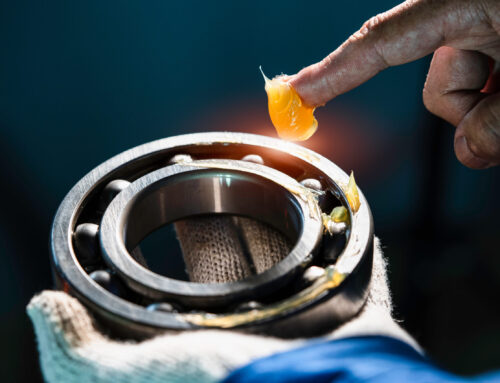
Bond integrity and minimum wall
A continuous, void-free bond from steel or bronze backing to Babbitt is non-negotiable. The final wall must be thick enough to avoid stress cracks, yet thin enough for good heat transfer to the backing and housing. With centrifugal casting, we can control as‑cast thickness tightly, then machine to the specified final wall while preserving bond quality across the load zone.
Understanding babbitt bearing clearance
What clearance really does
Babbitt bearing clearance sets the gap between the shaft and the finished bore. That gap fills with oil and creates the hydrodynamic film that holds the rotor off the metal. If the gap is too tight, you risk metal-to-metal contact when the shaft expands with heat or when passing through critical speeds. If the gap is too loose, the oil film loses stiffness, the rotor can whirl, and vibration increases. The right babbitt bearing clearance balances film thickness, load capacity, cooling, and stability.
Assembly clearance vs operating clearance
Assembly clearance is the cold diametral clearance measured at room temperature. Operating clearance is the effective clearance at running temperature. It can be smaller due to shaft growth, housing growth, and temperature gradients. This difference is why a bearing that measures fine at the bench can wipe during a hot run. Experienced facilities like Fusion Babbitting factor thermal growth into the recommended clearance window for your machine.
General clearance guidelines
Exact numbers depend on speed, load, oil viscosity, and geometry. As a broad rule of thumb for many industrial journal bearings:
- Slow to moderate speed, heavier load: about 0.001 to 0.0015 in per inch of shaft diameter
- General-purpose rotating equipment: about 0.0015 to 0.002 in per inch
- High-speed or high-temperature service: about 0.002 to 0.003 in per inch
These are starting points. API-style designs, OEM specs, and special duty machines may set different targets. When in doubt, contact Fusion Babbitting with your shaft diameter, speed, oil grade, and duty cycle to confirm a safe clearance.
Profiles, reliefs, and grooves affect effective clearance
Final clearance is not set by bore size alone. Crowning, taper, offset, and oil groove geometry all change how the film develops. An axial groove that is too wide can reduce load capacity. A parting-line relief that is too deep can starve the crown. When we rebuild a bearing, we match not only the nominal clearance but also the profile that supports the original oil wedge design.
A simple workflow to size and verify clearance
Step 1: Confirm the baseline
Collect the shaft diameter, speed in RPM, expected load, oil type and viscosity, housing fit, and ambient and operating temperatures. If a twin or sister machine runs well, note its clearance and geometry. Fusion Babbitting often uses a proven sister bearing as the baseline for new or reverse engineered units.
Step 2: Choose a clearance target
Using the rules of thumb and any OEM guidance, pick a cold diametral clearance target. Include a tolerance. For example, 0.002 in per inch of diameter on a 6.000 in shaft suggests about 0.012 in diametral clearance, often held within plus or minus 0.001 in depending on the application.
Step 3: Account for thermal growth
Estimate shaft and housing growth. Steel shafts expand about 6.5 to 7.5 microinches per inch per degree Fahrenheit. High oil temperatures, hot rotors, and tight housings all reduce operating clearance. Adjust the cold clearance upward if the machine runs hot or spins at very high speed. Fusion Babbitting can help run these thermal checks so your operating clearance stays in the safe zone.
Step 4: Select the final machine thickness and geometry
Confirm the minimum final Babbitt wall at the crown and parting lines. Verify groove sizes, relief depths, and edge chamfers. Set the bore finish and roundness tolerance so the oil film can form consistently. The final machine thickness must support the selected clearance and geometry without leaving thin, weak areas near the bond line.
Step 5: Set the as‑cast thickness
Pick an as‑cast thickness that gives enough stock to machine all features while avoiding waste. For example, if you need 0.090 in final thickness and plan to cut grooves and reliefs, an as‑cast thickness of 0.150 to 0.200 in may be appropriate, depending on the size and process control. Centrifugal casting at Fusion Babbitting delivers uniform as‑cast layers that finish predictably.
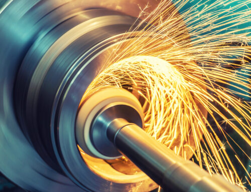
Step 6: Machine and measure
After casting and stress relief as required, rough bore the bearing, cut grooves, then finish to size. Measure bore size with a calibrated two-point or three-point bore gauge and verify roundness. Check final machine thickness at the crown and across the parting lines. Record the actual cold diametral clearance using the exact shaft diameter or a certified plug.
Step 7: Document and mark
Stamp or tag the bearing with measured cold clearance, material, and serial number. Create a simple inspection report. This documentation reduces guesswork at installation and helps future rebuilds run faster.
Inspection and quality checks that prevent failures
Bond and thickness checks
After casting, verify a sound bond and consistent as‑cast thickness. Common checks include ultrasonic bond inspection, light dye penetrant on suspicious areas, and a visual inspection of the bond line after a witness cut if required. Final machine thickness should be measured at marked stations and recorded.
Bore geometry and finish
Check bore size, roundness, taper, and surface finish. A smooth, consistent finish supports stable oil film formation. Pay attention to edge breaks and deburring around oil grooves to prevent scoring the shaft during installation.
Bearing crush and fit
For split shells, confirm bearing crush at the parting line and the correct interference fit in the housing. Insufficient crush can cause the shell to spin. Excessive crush can distort the bore and close the clearance. Fusion Babbitting inspects crush height and housing fits to keep alignment true and clearance consistent.
Blue contact check
A light Prussian blue contact check with a dummy shaft or mandrel can reveal high spots before the bearing ever sees service. It is a quick, low-cost step that protects a new rebuild from an early wipe.
Common pitfalls and how to avoid them
- Confusing as‑cast thickness with final machine thickness. Always confirm which value is specified and where it applies.
- Setting clearance by bore size alone. Include thermal growth, groove effects, and profile reliefs.
- Ignoring housing and cap alignment. Misalignment can reduce effective clearance on one side and wipe the film.
- Skipping bond checks. Small voids can grow into cracks under load and heat.
- Over-polishing the bore. Too smooth can reduce oil retention. Follow the finish required by the OEM or proven practice.
- Forgetting to document measured clearance. Field teams need this data during installation and startup.
When to rebabbitt or rebuild
If you see wiping, heavy scoring, fatigue cracks, fretting at the bond, or uneven wear near the parting line, it is time to inspect thickness and clearance. A rebuild can include stripping the old Babbitt, restoring the backing by arc flame spray if needed, and recasting with certified alloy. Fusion Babbitting provides 24-hour emergency services when a critical machine is down, and we can reverse engineer obsolete bearings using detailed measurements and drawings so your team is not stuck waiting on an OEM with long lead times.
Fusion Babbitting capabilities and services
Fusion Babbitting Co., Inc. has served industry since 1988 from our facility at 4540 W. Burnham St., Milwaukee, WI. We repair, rebabbitt, and rebuild Babbitt bearings to meet or exceed OEM specifications. Our team handles components up to 120 inches in diameter and length, and we support customers nationwide with around-the-clock emergency response.
- Repair, Rebabbitting, and Rebuilding: Proven processes that meet or exceed OEM tolerances and restore full performance.
- Centrifugal Casting: Uniform, strong bonds and controlled as‑cast thickness using certified Babbitt alloys.
- Arc Flame Spray Application: Restores worn housings and journals, then we machine back to spec.
- Reverse Engineering: Accurate replicas of obsolete bearings with professional drawings and material specs.
- General Fabrication and Machining: Large-capacity equipment for precise boring, grooving, and finishing.
- New Manufacturing: Custom, high-precision bearing products for OEMs and upgrades.
With over 40 years of combined expertise, Fusion Babbitting focuses on reliability. Whether you need help determining babbitt bearing clearance for a pump rebuild or want a full reverse engineered set of turbine bearings, our specialists deliver fast, reliable results.
Industries and applications we serve
Fusion Babbitting supports a wide range of heavy and light industry. Our work helps keep continuous processes running, from mills to power generation.
- Aluminum Mills
- Cement and Chemical Plants
- Fossil and Nuclear Plants
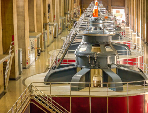
- Hydro and Pump Storage
- Marine Repair and Shipyards
- Mines and Steel Mills
- Motor Repair Shops
- Paper Mills
- Crushed Stone Producers
Common applications include electric motors, hydro power systems, pumps, and turbines. If your equipment depends on a stable oil film, we can help you get the clearance, thickness, and geometry right.
Example: turning specs into a reliable rebuild
Imagine a 5.000 in shaft in a process pump that runs warm with ISO 68 oil. A good starting target is about 0.0015 to 0.002 in per inch of diameter. That suggests 0.0075 to 0.010 in diametral clearance cold. The pump operates at a high enough temperature that the shaft might grow a few thousandths in diameter. To protect operating clearance, you could select 0.009 in diametral cold clearance with a plus or minus 0.001 in tolerance and verify the housing fit to avoid distortion. Final machine thickness could be specified at 0.080 to 0.100 in at the crown, with parting line relief per the OEM’s drawing. Grooves are sized for flow without robbing the load zone. During inspection, you would check the bond, measure the bore, verify roundness, confirm crush, and document the actual cold clearance. This process reduces the chance of a wipe on first startup and keeps vibration within limits.
Key takeaways you can use today
- As‑cast thickness is the raw layer after casting. Final machine thickness is the minimum wall that remains after machining. Do not confuse them.
- Babbitt bearing clearance should consider shaft diameter, speed, load, oil viscosity, and thermal growth. Use proven ranges as a starting point and verify with your application data.
- Profiles, grooves, and reliefs change effective clearance. Match the original geometry or work with experts to set a stable oil wedge.
- Inspect bond integrity, final thickness, bore geometry, and crush. Document cold clearance for the field team.
- If drawings are missing, reverse engineering by Fusion Babbitting can recreate specs, including thickness and clearance, and provide detailed prints.
Need help sizing or inspecting a bearing? Contact Fusion Babbitting
If you want a second set of eyes on babbitt bearing clearance, or if you need a fast rebuild that meets or exceeds OEM standards, talk with Fusion Babbitting. Our specialists can review your application, confirm as‑cast and final machine thickness, set a safe clearance target, and deliver a complete inspection record with your rebuilt bearing.
Fusion Babbitting Co., Inc. 4540 W. Burnham St., Milwaukee, WI 53219 Phone: 414.645.5800 Toll-Free: 800.613.5118 Email: sales@fusionbabbitting.com
From emergency repairs to full reverse engineering and new manufacturing, Fusion Babbitting keeps your equipment running safely and efficiently. Reach out today for a quote or a quick clearance check, and put our experience to work for your next bearing rebuild.